Types
Load banks simulate “real world” electrical power loads within commercial facilities such as office buildings, hospitals, data centers, and shopping malls. Typical real-world loads include lighting, electric motors, computer systems, and heating and cooling systems. Read more about various load bank types below.
RESISTIVE LOAD BANKS
A resistive load bank, the most common type, proves equivalent loading of both generator and prime mover. That is, for each kilowatt (or horsepower) of load applied to the generator by the load bank, an equal amount of load is applied to the prime mover by the generator. A resistive load bank, therefore, removes energy from the complete system: load bank from generator—generator from prime mover—prime mover from fuel. Additional energy is removed as a consequence of resistive load bank operation: waste heat from coolant, exhaust and generator losses, and energy consumed by accessory devices. A resistive load bank impacts all aspects of a generating system.
The “load” of a resistive load bank is created by the conversion of electrical energy to heat by power resistors. This heat must be dissipated from the load bank, either by air or by water, by forced means or by convection.
In a testing system, a resistive load simulates real-life resistive loads, such as lighting and heating loads as well as the resistive or unity power factor component of magnetic (motors, transformers) loads.
REACTIVE LOAD BANKS
A reactive load includes inductive (lagging power factor) and/or capacitive (leading power factor) loads. Inductive loads, the more common type, consist of iron-core reactive elements, which creates a lagging power factor load when used in conjunction with a resistive load bank. Typically, the inductive load will be rated at a numeric value of 75% of that of the corresponding resistive load such that when applied together, a resultant 0.8 power factor load is provided. That is to say, for each 100KW of resistive load, 75KVAR of the inductive load is provided. Other ratios are possible to obtain other power factor ratings. Inductive loads are used to simulate real-life mixed commercial loads consisting of lighting, heating, motors, transformers, etc. With a resistive/inductive load bank, full power system testing is possible, given the impact of reactive currents on generator/voltage regulator performance as well as effects on conductors and switchgear.
WATER-COOLED LOAD BANKS
Water-cooled load banks allow for indoor installations in controlled environments rather than outdoor installations, where units are exposed to the elements. Besides being completely quiet, the water-cooled load bank is highly compact and virtually maintenance-free. They are ideal for installation in buildings in central-city areas, industrial parks, or office complexes where an outdoor air-cooled unit would be architecturally obtrusive or impossible to install due to space or noise restrictions.
Safety
Load banks are not inherently dangerous, but there are dangers that exist with the operation of load banks. This is a technical, industrial product and should only be set up and operated by trained, technical personnel who are specifically authorized.
Be certain that all equipment is properly grounded. Carefully check cables for wear and tear and insulation damage. Check all camlock connectors and that connections are made sound and tight, including connector mating (the connector twist-tightens) and the cable within the connector.
Be certain that cables are phased correctly. A circuit breaker or fuse set is required at the power source, sized appropriately for the conductor run.
Be sure to run adequate ampacity of cables. Check that the generator voltage corresponds to the load bank voltage. Check the correct airflow direction, and if it is necessary to reverse the cooling fan direction, allow the fan to fully stop before reversing. Provide the CFM required at an ambient not to exceed 125°F.
Be observant of airflow restrictions and re-circulation of airflow. Be careful that foreign objects are not drawn into cooling intakes.
Do not operate indoor load banks in the rain.
Observe common and accepted practices when operating high-voltage electrical equipment.
Note that the load bank exterior, exhaust screens, and other sheet metal parts can be very hot. Wear safety equipment and hearing protection as required.
Please contact 978-378-4636 if you have any questions.
Heating and Air Flow
The user needs to appreciate how hot a load bank gets and how much hot air is produced. As a guide, temp rise (°F) = KW x 3000/CFM. Load banks are heat producing devices and must be ventilated. Observe the CFM capacity of the load bank and be certain that equivalent air intake is provided. If operated indoors, be cautious to prevent recirculation of exhaust air and observe ambient temperatures.
Do not operate vertical airflow load banks under a close ceiling. Maintain a max ambient temperature of no more than 125°F. Load banks greater than 100kw (PowerStar 100) are ideally operated outdoors, and extreme caution should be exercised with units in the 100-700kw range. Above 700kw, an indoor space would have to be voluminous and well-ventilated. Indoors, note the presence of sprinkler heads as the load bank WILL ACTIVATE sprinklers very quickly. Outdoors, be observant of adjacent equipment, buildings, and plantings.
Operate in an area with a clear sky above. Avoid putting the load bank in a virtual pit by surrounding it with tall walls or buildings. Space multiple load banks 4-6 feet apart. A greater distance is required for larger units.
Calculations
Load Bank Calculations - Voltage, Current and KW
Voltage
Low voltage AC systems are rated 120/240v, single-phase, 2 or 3 wire; 208-240/416-480/575-600vAC, 3 or 4 wire. Medium voltage systems are in the 5kV or 15kV class.
DC systems can typically range from battery voltages of 12/24/32v, 125/250v, or 350/700v. Keep in mind that the AC load banks we showcase on our website are generally 3-phase, 3-wire loads, meaning that a neutral is not required and that loads are applied in 3-phase balanced steps.
Current
Current, expressed in amperes, is found by the following formula:

Current must be known in order to size connection cables. Keep in mind that connection cables have a certain small resistance, and that a small voltage drop will be seen across the cable set and at the terminals of the load bank. Therefore, although the generator instrumentation may indicate 480v, the load bank instrumentation will measure the terminal voltage at the load bank, for example, 473v.
KW as a Function of Voltage (De-Rating)
KW varies as the square of the voltage change and can be calculated using the following formula: KW output = Rated kW x (Applied Voltage/Rated Voltage)2. Therefore, in the preceding example, if the load bank terminal voltage is reduced to 473v, then the resultant KW will be 97% of the rated KW. Where did that power go? It is lost as heat in the connection cables.
Power Factor Testing
Power Factor Testing
Lagging Power Factor Testing (Adding Inductive Load)
By adding an inductive load to the resistive load, lagging power factor can be obtained. Commercial loads, as well as generator sets, are rated at the nominal power factor of 0.8 lagging. This number is the cosine of the angle made between the KW and the KVA in the diagram below:

The magnitude of inductive load required to obtain 0.8 power factor is 0.75 x the KW (1000kw + 750kvar = 1250kva at 0.8 lagging power factor). As a point of interest, 0.75 is the tangent of the aforementioned angle. Keep in mind when sizing cables that the full load current at the rated KVA must be calculated.
Leading Power Factor Testing (Adding Capacitive Load)
The same rationale as Low Power Factor Testing applies to leading power factor, except capacitive load is added. Leading power factor testing is rare and specialized. Most engine generator sets cannot tolerate more than a very small degree of leading power factor.
Troubleshooting
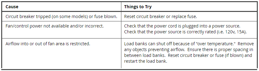
LOAD BANK COOLING MOTOR WILL NOT OPERATE
Symptoms
- When the unit is turned on, the controls light-up but the fan does not operate.
- When the unit is turned on, the controls indicate a fan cooling error.
- The fan operates for a brief period and then shuts off.
Possible Solutions
LOAD BANK TEST METERS WILL NOT OPERATE PROPERLY
Symptoms
- Test meters do not show the correct values.
- Test meters are blank or do not turn on.
Possible Solutions

LOAD STEPS CANNOT BE ENERGIZED
Symptoms
- You are not able to attain the desired capacity for your test.
- Load is not applied when one or more steps are engaged.
Possible Solutions

LOAD OVERVOLTAGE ERROR INDICATED ON CONTROLS
Symptoms
- Load removed from test without operator involvement.
- Load controls indicate an overvoltage error.
Possible Solutions